

Forum Replies Created
-
AuthorPosts
-
Reading others achievements, plays part to get motivated yourself.
All the rods/linkages free free, but i will lube it before it all gets closed up.Sounds like I had the same trouble as you. Most of those holes on the hoz-lip rotted out.
8 small plates in all had to be inserted in. There was only a few inches between them of original sill.
Luckily though they didn’t have to go far ‘up’ the sill, mostly just to the second fold-line, where the outer-face starts.I got the drill-kit too, unsure which size. Comes with a few spare cutters & a drill-bit cutter. I found using the drill-bit best for making a ‘dip’ for the sprung-pointer after limited success with a dot-punch. Kept spinning itself off centre.
Today I double-bagged the car for the winter. I use those halfords car-covers. They look to work quite well. Uncovering after last winter the car was bone-dry. But it’s often windy where I am and it can ‘ballon’ somewhat with gusts. I think it helps circulation. For added integrity, I strap it down too around the base of the front & rear screens. Plus i have added eyelets to the front and rear hem of the outer-cover, then bungy it secure underneath.
Over the good days through september i’ve managed to repair the C-post & sill on the NS of the car.
The C-post initially looked like it wouldn’t need much. But as usual, once you started diggin’ in, it was as bad as the OS.
I had to put several small patches into the sill-apron lower edge. It would have been easier to simply get a repair panel and weld the entire lower edge in. But I didn’t have one and couldn’t wait for the days taken to get one.
Since doing the OS, I’d purchased one of Machinemart spot-drill cutters. The ones that are like a mini hole-saw. I found it much better than a drill-bit type. As i found these often, suddenly, if not very careful cut through the entire metalwork. With the hole-saw type, it effectively leaves the ‘spot’, but thats is nicely dealt with removing with flap-wheel, rotary-file etc leaving a good base for the new plug-weld.
Most of the rot cut out. I ended up cutting the rear-side more, cutting it higher.
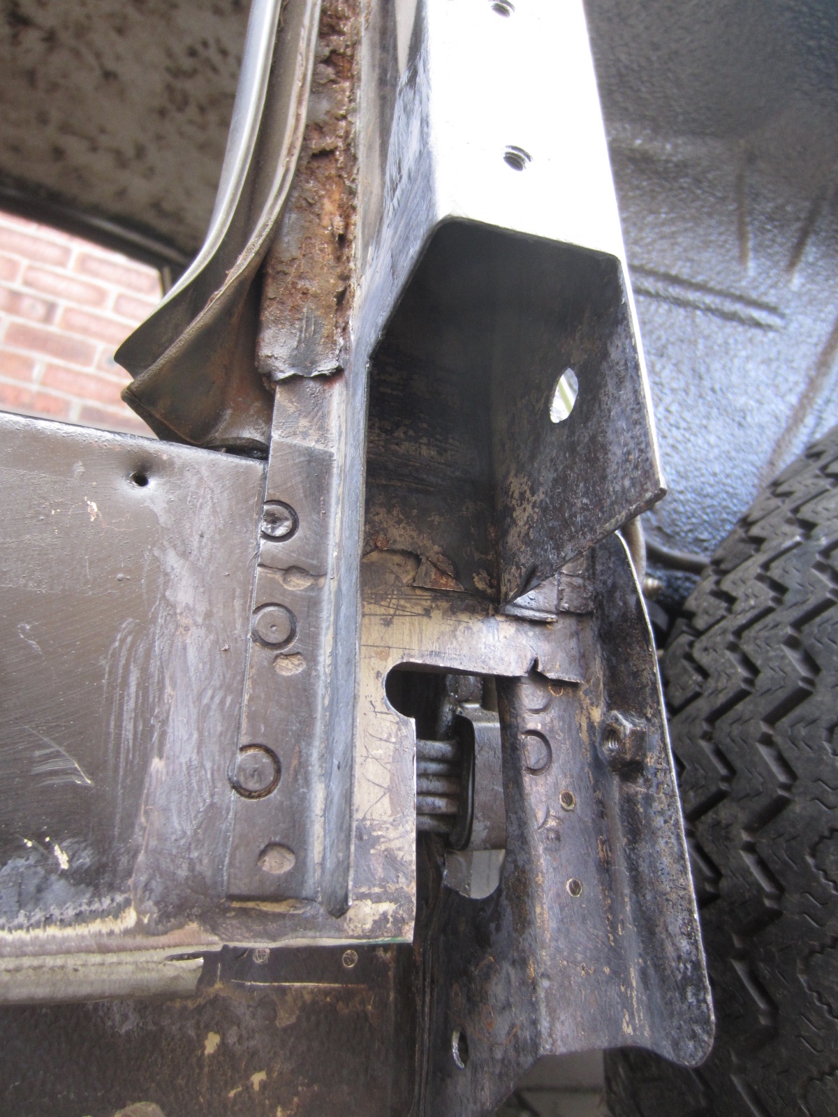
Small repair patch to inner panel + the lttle tab that secures it underneath.
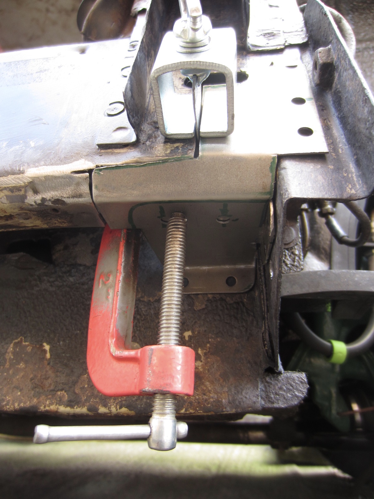
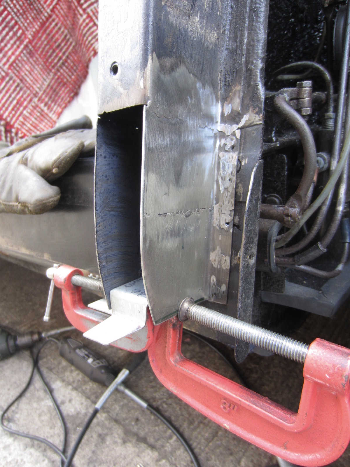
Starting to take shape. Had to re-shape the seal-holder, as typically it was badly formed.
Metal-work done. Still ned to tidy it up with filler etc, but that has to wait until next summer now.
Can see the door-seal-channel is quite bad here too.
I replaced all the very lower parts of the door-seal-channel. But the others were only 3-4 inches in length.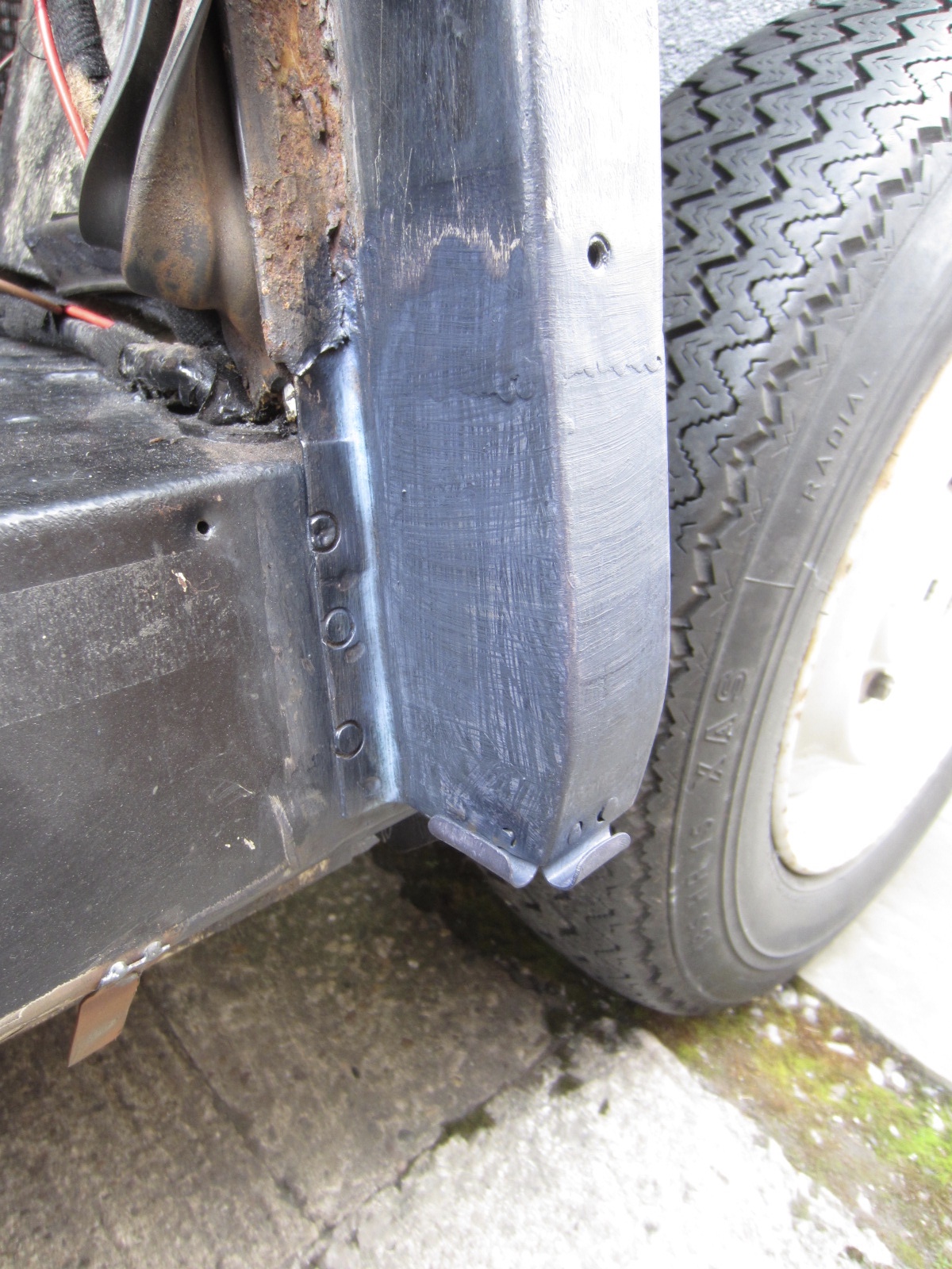
Rotten channel removed, until it gets good enough to leave it.
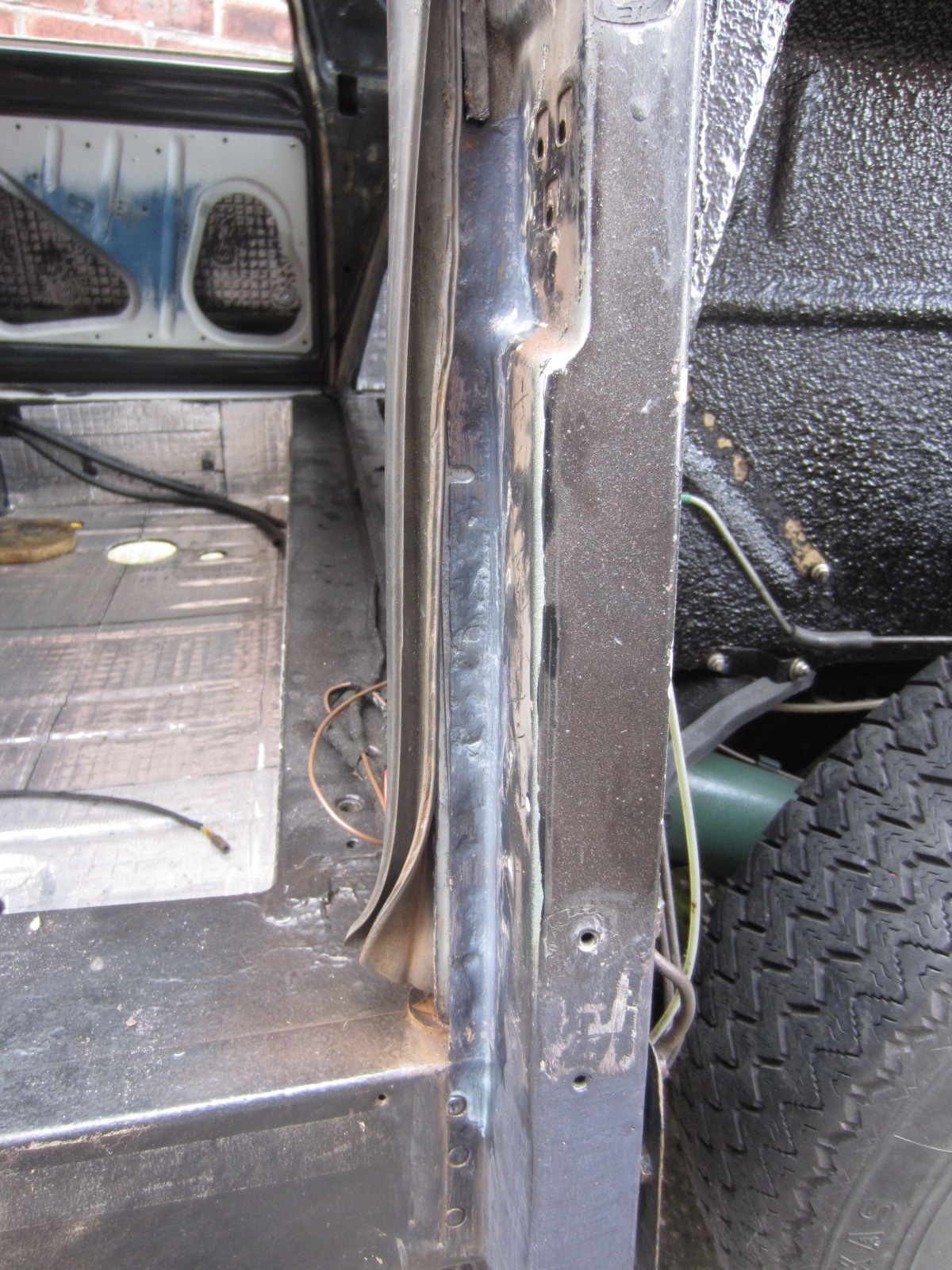
New seal-channel tacked in, it goes up to about half way, but thankfully all a straight piece.
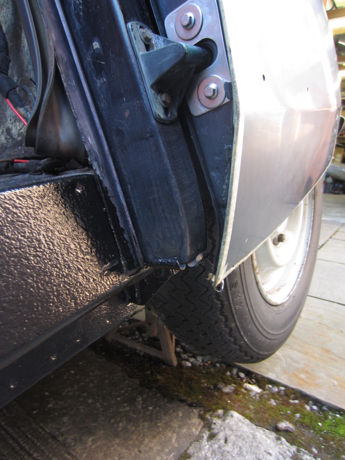
Fwd section of sill. Apart from that very lower edge the sills are good. There was some underseal/coating, which has obviously saved them. I scraped off what i could, cleaned it all up, added hydrate-80 to surface rust patches and applied couple of coats of Jotum 90. ALl the hydrau-pipes are good. I cleaned them with a 3M pad and coated with hydrate 90 in effort to preserve them going forward.
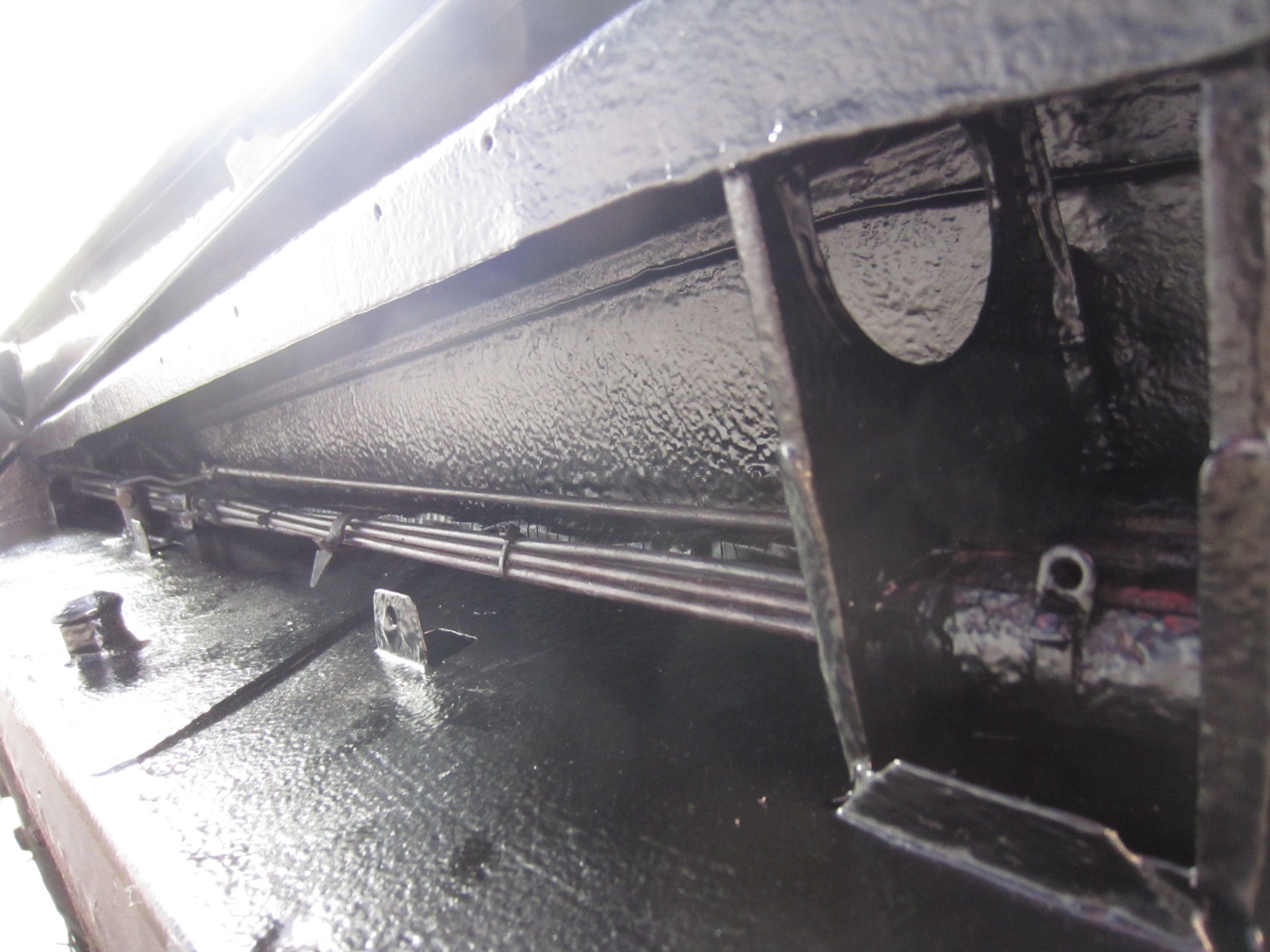
Aft sill section. When they get boxed up i’ll spray some dinitrol or something in there, just for an additional layer of protection. Though it’s all fairly well coated now.
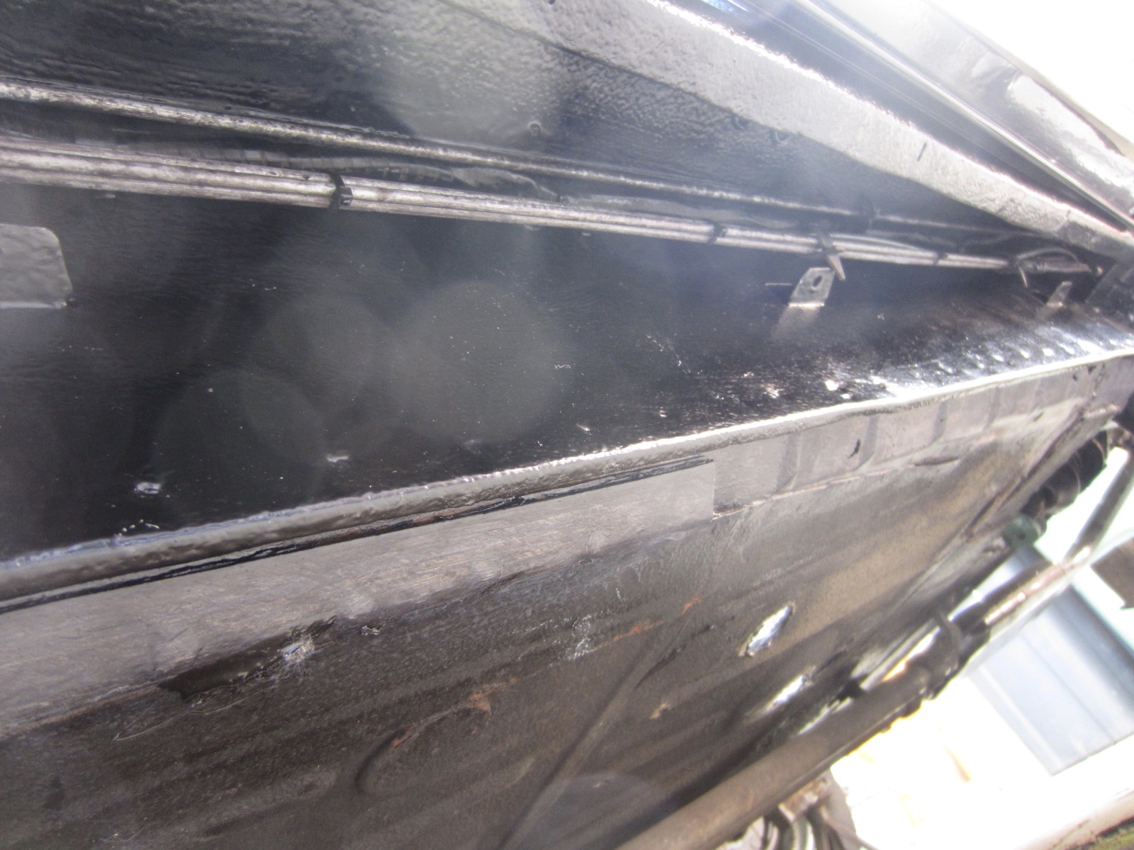
Oh, I also replaced the little ‘C’ channel that holds the bottom seal on the B-post. Luckily the post itself was pretty good. Couple of holes i welded in small round-patches about the size of a halfpence.
Next summer I can prep & apply paint and add the covers. Then, finally I can see about the bloody carpets.
no bother, offers there.
very neat with the brass tube.
Doesn’t matter it’s not seen, you know it’s there.
We all do the same, go to unnecessary lengths for stuff that ultimately doesn’t matter.Definitely inspect mine come the time. It won’t be until next spring/summer now.
It’s presently all exposed, so before all the covers go back on for sure.Good job on the clean up & recal.
That pressure tester looks a brilliant piece of kit.
How bad is the broken case, do you have all the parts or at least most for reference?
I’m thinking it’s an ideal thing & easy by the looks of it to 3D-print a new one?
Do you have access to a printer?
If not and you’d like, i can print some on my next period at work?
how did you deal with the rivet after, presumably drilling off the rolled edge?To add to Pauls info on understanding the wiring, you might be lucky and it is a bad connection.
The fact that the terminal is getting hot is text-book high-resistance.
When the circuit is active, lamp on, current flows.
That current flowing will have power described by I^2R, that is the Current ‘squared’ times the Restistance.
Normally connections; relay-contacts, spade-terminals, bullet-connectors & lengths of wire all have negligible resistance, so the power is negligible itself and all is good.
With a bad connection that resistance is increased and with that the power increases to the point that it generates enough heat to get hot or burn/damage.
Also there is a voltage created across that connection described by ‘IR’, that is Current times Resistance. This voltage manifests as a voltage-drop & in normal circuits it is again, negigible, leaving all the source voltage for loads.
But in that high-resistive situation it can be significantly larger, reducing available voltage for any load and typically preventing it from working properly.
going back to your blog paul, i’ve used it numerous times for reference with my own works. it proving very, very useful. I thank you for all the attention and detail you put into that.
yeah, those lamp covers are cool. agree, nice detail like that are worth the effort.
i need to re-evaluate all my driving/headlamps for reflector-condition.
but, those cibies is that somehting you can get new or are they nos items?i think your approach to the car is spot on.
engine bay looks fantastic.you’re right, there a lots of ameteur folks out there doing incredible work on all sorts vehicular.
I think, when you try and do stuff yourself to the best outcome given facility and ability. Often not reaching the result you have in your mind, accepting them, living with them etc. Based on ones own efforts, you very much appreciate high-end workmanship & attention to detail of others.Reading the back story to your car, I drew numerous parallels with my own story: Car stored hours away from home, impossible to get anyhting done. Life getting in the way, times when you simply forgot you had the car. Frustrations with the situation, thoughts of giving up and it goes on.
Seeing what you have achieved and the journey to get there, I say again, truely inspirational.
Spectacular Paul.
Commitment, patience, endeavours, quality of work and it goes on and on.
Truely inspirational.
I wish you many, many happy years with that car.
Outstanding.Yeah, i can do that.
The intention was for it to be a learning-curve or experiment in what was possible.
If it comes to nothing or gets ruined in the process, no big deal.I have found some seals that look very promising too.
Vulcan Type 18, 70 & 75. As well as others Type 60 & 65.
Dimensionally compatible & possible.not much more to report on this other than i pressed the impeller shaft out.
It came out real easy. I use floor standing 30T press, but it took no force at all to push out.I’ll get some 12mm ground bar to replicate it, save messing about sleeving. filling those pits.
I did think, you could reverse the shaft and place the nice smooth end into the impeller. Those small bearings wouldn’t care about the pitted shaft.While i was at it, i took 0.3mm off the cast-seat to get rid of the rings/grooves.
Nice and smooth now. Plan to ‘lap’ the graphite seal to clean it up, shouldn’t take much.
Then decide do i put it all back together or try and implement an alternative seal?Made a stainless spacer for the bearings. Original, though fits on the shaft nice and runs smooth.
Is heavily corroded on the outside. Doesn’t really matter about that, but seeing as i was on the lathe…
yeah.
I wonder what the configuration is of water pumps on other cars, earlier models from back in the day to more modern stuff. My recollection is that water pumps on the whole weren’t a common failure? Never had a water pump fail/changed on any of the cars, bangers & otherwise i’ve had in my motoring life?Yes, I’ve come across those shaft-savers. Can’t recall the correct name.
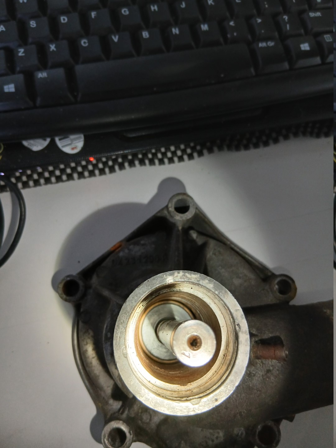
I still think i’d have a go at removing the shaft from impeller before messing about with one of those?photo of the seal from the impeller side. You can see the rubber face that seals against the central-boss of the impeller. The spring within the cupped-body that applies tension to the sealing faces, both front & rear graphite when the pulley is pressed on. How far you press it on dictates that tension. There’s also an internal rubber face, about 10mm in length/width that seals around the shaft too. In fact that rubber part is like a rubber cylinder/boss/slug ~18mm OD, 12mm ID & 10mm thickness. Pressed into the brass housing.

photo of the seal fitted to shaft/impeller. Here the rubber-face sits against the impeller-boss. That thin lip you see is not the rubber-face, but part of the, looks brass housing. It (the lip) has the spring against it and it is that thin metal lip that pushes the rubber-face against the boss. Hope that makes sense?

I conclude that this seal is the ‘rotary’ part and spins with the shaft. So possibly a slightly pitted shaft could be compensated for with some, i’m thinking thread/pipe-sealant on the faces that contact the shaft & impeller-boss?
Photo of the pump housing from impeller side. So pressed into that bore goes the cast-seat. You can see one of the drain-holes to align with one on the seat. The graphite-face of the rotary seal then runs against the face of the seat

Photo showing the seal with graphite face, as would be installed, looking down the shaft. imagine that cast-seat in there with two faces together.
The threads on the following post…
https://www.aussiefrogs.com/forum/index.php?threads/dspecial-waterpump-seals.151663/
talk about it, it’s mentioned that repro pumps use integral-bearings and appear to be difficult or not possible to press apart? Look to be a simpler non-serviceable design from what folks say? I think i’ve found a possible alternative seal based on thread #13 and this type ’68’ seal that is mentioned.
It does seem a lot of phaff to modify in order to take an alternative seal; machining parts to fit etc. But, I suppose if time, facility and ability is to hand, then why not have a go? Forgetting the pulley for now. I guess as long as the pump-body and impeller are intact all else is replaceable? Even the shaft could be remade, if desired. One above is a little pitted around where it passes through the seal. Not sure that matters too much as there is nothing sealing around that shaft area. Only with the rubber-lip at the shaft/impeller fit.

I’m tempted to have a go at pressing the shaft out. I think supported properly on the central boss, bit of heat maybe and the shaft should come out easy with impeller intact?
Bearings are easy, can’t recall the exact numbers, but a few quid from anywhere. I’d definitely go with the best fully sealed available. They’re pretty cheap.
keeping it simple, I thought the same about the seal: Resurface the cast-seat and possible lap the graphite face on the seal itself? Not visible from my photo’s, but the seal has a cuped-spring affair and a rubber lip that sits against the face of the inner-boss of the impeller. Correct amount of preload should be put on the spring for optimal seal/wear characteristics. I don’t know how you’d set that up with an alternative seal. You’d have to get the dimensions/spec from seal manufacturers how to set them up?
I should have measured how deep the impeller shaft was against the pulley. That way i’d have an idea about pressing it back together and applying appropriate force on the seal, taking into account any changes from machining/lapping? I’ll put a descent photo up of the spring side of the seal.
The cast seat has holes in it and these align with holes in the pump body. Look to be vent/drain. Any water that creeps past the seal gets drained off looks to be the idea. The pump body/cast-seat was fairly clogged up.
i wonder how a zerk-fitting and pack it with grease would perform?As mentioned before, no need to grind those rivets off. Just press the shaft straight out in a one’r. A bit of heat on the pulley would likely make things easier. It was on a big press, didn’t notice the gauge before it started to move. Few tonnes maybe?
I don’t know where this lot will go, whether it simply be an exercise to satisfy curiosity or see what is possible and end up an actual modified/recon pump. It’s got to start with a suitable alternative seal, as the rest is straight forward really.
some photos of the disassembled pump.
Probably won’t do anything with it anytime soon.
When back at home, i’ll look into a compatible seal and what is required to install.
more out of interest than necessity.order of parts on the shaft.


mechanical seal graphite-face & cast seat-face.

cast-seat rear-face & small bearing

rear-face of pulley

front-face of puller, ground rivets, no need to have done so.

pump body

yes, it is a factory pump.
I’ve read somewhere, on here i think? Rivets fracturing, so folks welding pulleys for reinforcement.
There’s definitely scope for strategic welding, just won’t look as nice as before?
Possibly replace rivets with cap-screws?I found some descriptions on aussie-frogs of folks modifying them for other mechanical seals.
Some machining involved, but that is not a problem.
So I am still intrigued of the possibility to repair/recon a pump with lasting results.I’ll load some photos of the parts, be a reference if nothing else.
-
AuthorPosts