
Forum Replies Created
-
AuthorPosts
-
Hydraulic pressure switch and associated warning light now working as Andre intended 🙂
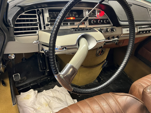
After I’d discovered that mine worked in a bench test, but operated at only 22 KG/cm2 (about 22 bar), I temporarily refitted it to the car. Frustratingly – it didn’t work on the car!
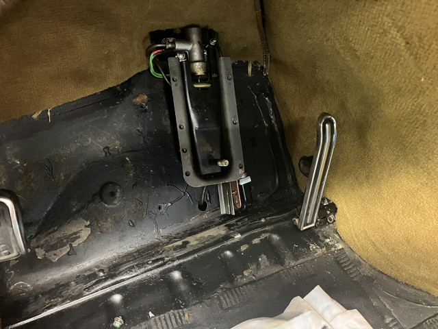
I got another from Holland and, on testing, it worked at 60 bar – just on the margins of ‘in spec.’. I removed my old one again and decided to recalibrate it while i was at it – just for the learning. It was no good as it was. It proved easy to re-calibrate but in removing the rivet holding its case on, the drill slipped and shattered the plastic case.
That being so, I planned to fit the other one I’d got from holland. But I decided to slightly recalibrate it so that it was in the middle of spec. About 65 bar. I could also clean the contacts. I removed the cover (carefully this time) and this is what i found. Piles of rust! It had looked fine from the outside.


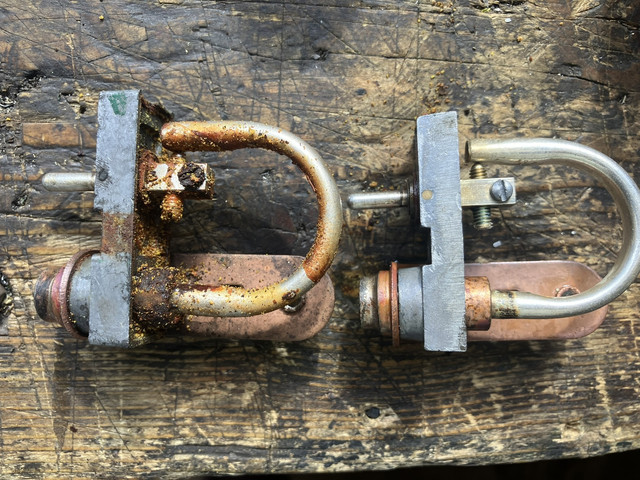
I’m so glad i didn’t just fit it in its 60 bar mode! In the end, i’ve used my original switch – recalibrated to 64 kg/ cm2 – and used only the cover from the spare i bought.
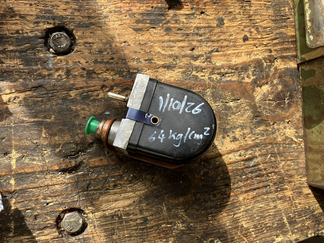
I think I’ve worked out why – when still in its 22 bar mode – it didn’t work when refitted. I’m guessing that there is residual pressure in the switch that is not released when the engine is turned off or even when the pressure regulator bolt is loosened. After refitting and starting the engine, I think pressure in my car didn’t drop to 22 bar or below – so my light never came back on. I think that – again, when it was in its 22 bar mode – if I’d opened the brake bleed screws, pressure would have dropped to zero and my light would have come on – but it still needed fixing.
Now that it’s correctly recalibrated, if pressure drops to anything below 64 bar the light will come back on. And, if my theory is correct, there can’t be that much residual pressure in the system.
Next/ last job is to bleed the front brakes again. then i can investigate the suspected air ingress on my carb.
Hydraulic pressure switch and associated warning light now working as Andre intended 🙂
After I’d discovered that mine worked in a bench test, but operated at only 22 KG/cm2 (about 22 bar), I temporarily refitted it to the car. Frustratingly – it didn’t work on the car!

I got another from Holland and, on testing, it worked at 60 bar – just on the margins of ‘in spec.’. I removed my old one again and decided to recalibrate it while i was at it – just for the learning. It was no good as it was. It proved easy to re-calibrate but in removing the rivet holding its case on, the drill slipped and shattered the plastic case.
That being so, I planned to fit the other one I’d got from holland. But I decided to slightly recalibrate it so that it was in the middle of spec. About 65 bar. I could also clean the contacts. I removed the cover (carefully this time) and this is what i found. Piles of rust! It had looked fine from the outside.
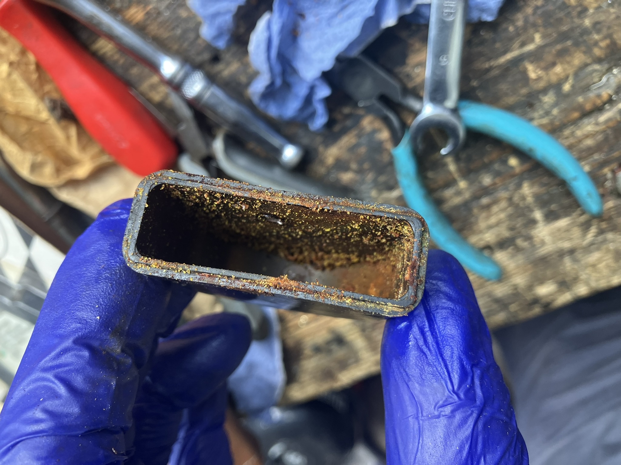
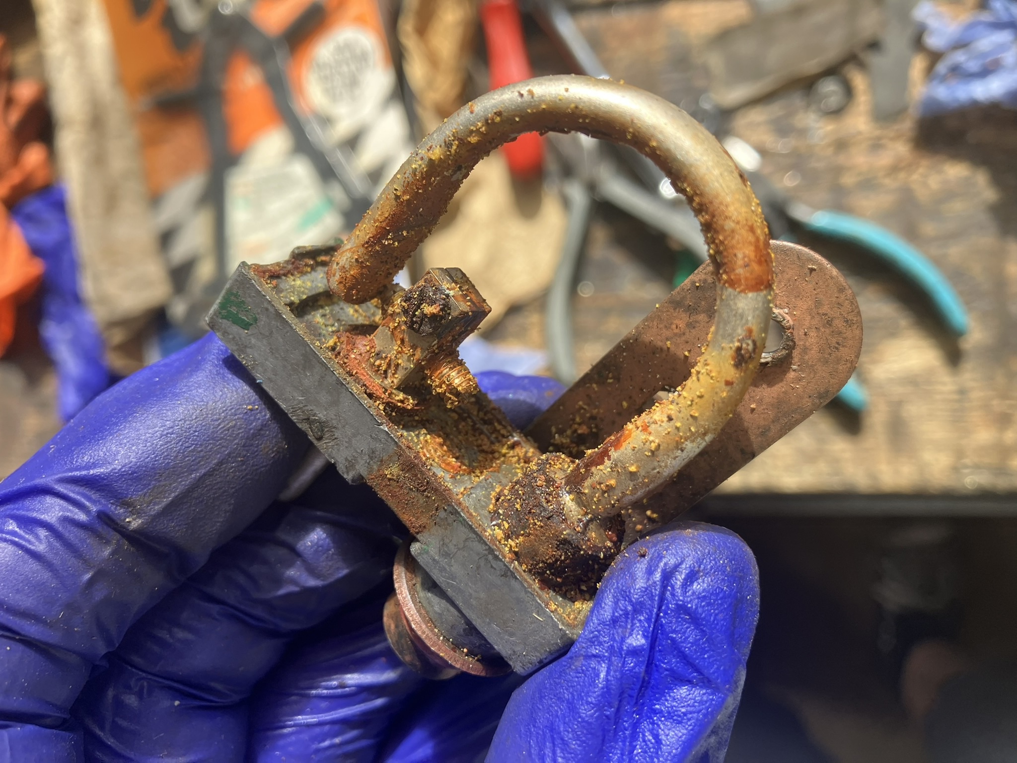
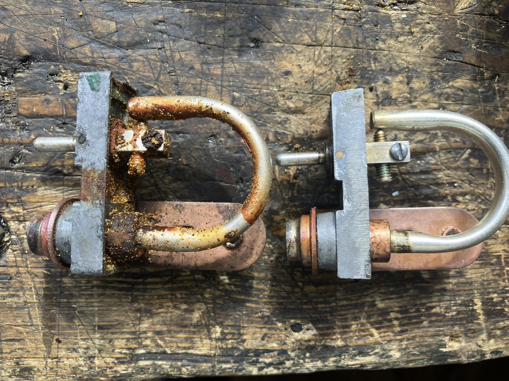
I’m so glad i didn’t just fit it in its 60 bar mode! In the end, i’ve used my original switch – recalibrated to 64 kg/ cm2 – and used only the cover from the spare i bought.
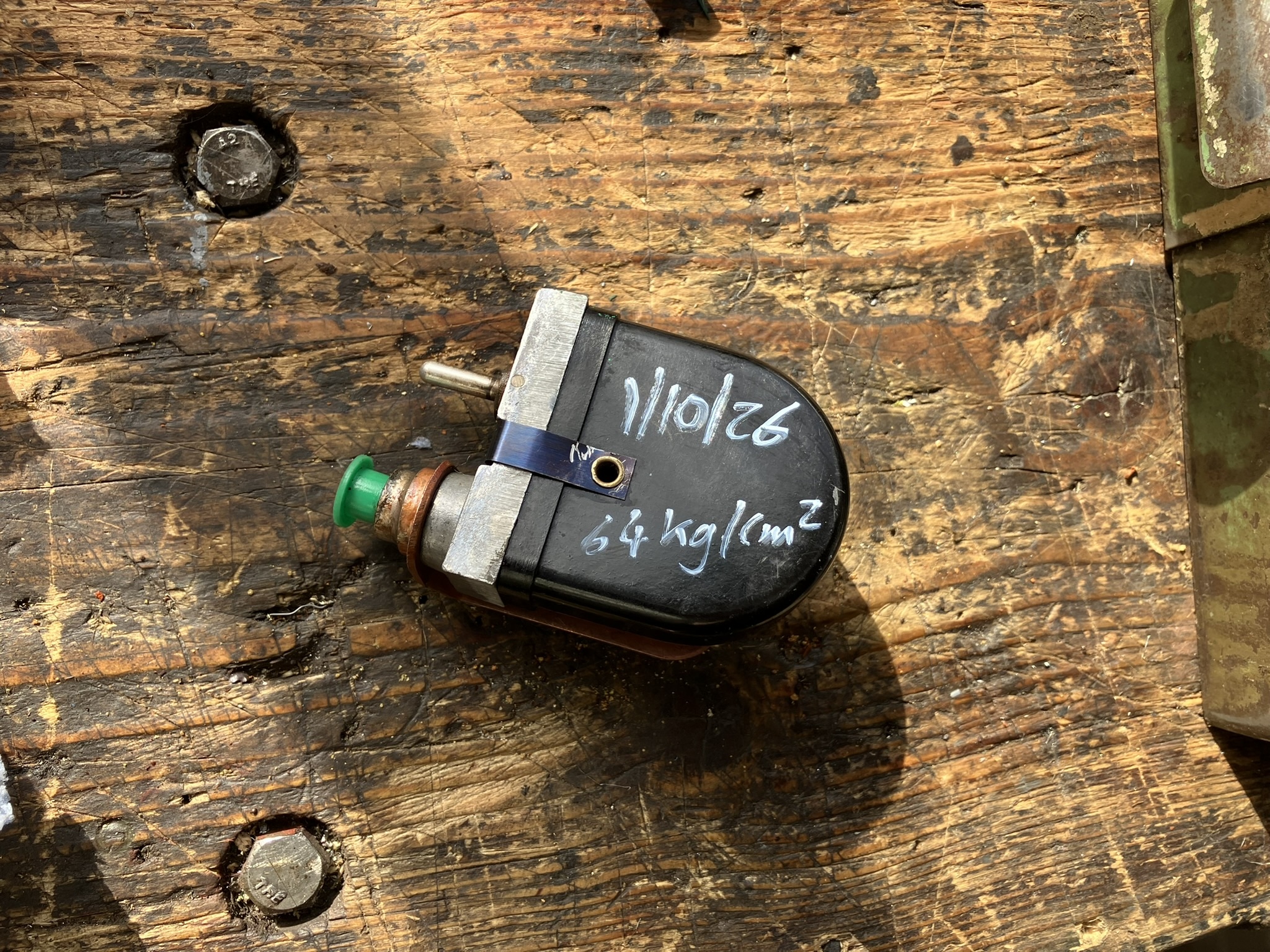
I think I’ve worked out why – when still in its 22 bar mode – it didn’t work when refitted. I’m guessing that there is residual pressure in the switch that is not released when the engine is turned off or even when the pressure regulator bolt is loosened. After refitting and starting the engine, I think pressure in my car didn’t drop to 22 bar or below – so my light never came back on. I think that – again, when it was in its 22 bar mode – if I’d opened the brake bleed screws, pressure would have dropped to zero and my light would have come on – but it still needed fixing.
Now that it’s correctly recalibrated, if pressure drops to anything below 64 bar the light will come back on. And, if my theory is correct, there can’t be that much residual pressure in the system.
Next/ last job is to bleed the front brakes again. then i can investigate the suspected air ingress on my carb.
I agree Colin. Those yellow H1s look fine.
I bought some yellow P45T bulbs for my headlights from Citroen Classics – 2 to fit and 2 as spare. The two I fitted had ‘burnt’ with only about 1 hour of use. The filaments haven’t failed. The yellow paint/ coating has burnt and gone dark brown on one side of the globes, meaning the light isn’t penetrating…..
i’ll try the other two but some/ all might be going back for a refund.
Late 1967 DS21 Pallas:
If the internal circuitry was understood, then one could surely get one or wire up more than one modern relays to do the same thing.
Best Regards,
Michael (Isle of Wight)Below is an example of a modern relay that i think would do the same job. Do you agree Peter?
BUT I would go for easy first, and assume you’ve either got the relays muddled and so wired wrongly…..
Test each relay: unplug all the 4 pins and then put a test bulb or other tester/ meter between pins 2 and 3 and test for continuity. If it’s a relay for the QI lights, there should be NO continuity. So you should find two of your relays are like this. On the flash relay, pins 2 and 3 are in contact – so there should be continuity. You should onlu=y have one relay like this.
…..or have the correctly identified the flash function relay – but have it wired wrongly.
Pin 1 is a source of ‘flash’ power in from the INDICATOR stalk
(This source of power also provides the power to energise the relay solenoid coil)Pin 2 is OUT to the loom and on to the two main beams
Pin 3 is a source of power in from the TWISTY LIGHT stalk
Pin 4 is out to ground from the relay solenoid coil.
here is a Bosch example of a modern relay. Peter can confirm if this would do the same job as the Sanor.

And here is another. Different brand, same thing, same function.

Yep. Been inside those black domed Sanor relays….
If you’ve got three relays, then your car probably had/ has had a flasher feature. For a late 67 year/ early 68 model, if it only had two replays, they are the one for the QI/ long range lights.
If your car has a flasher (as the three relays suggest) then when you move the indicator leaver towards you, it should spring back – that’s the flash function. if, having put them on, your indicators are cancelled by pulling the lever towards you, then that particular switch unit DOESN’T have the flash function – regardless of what your relays suggest.
I can’t make out your nomenclature for your wiring diagram. On my diagram for sept 67 to december 67, part 20 is the alternator and part 40 is the cigar lighter?
The three relays behind the dash are not the same. Two ARE the same – they are one each for each of the QI lights.
The other one is for the headlight flasher. The normal high beam power passes straight through this in normal operation. By which i mean the high beams are not fed from the relay but ARE fed ‘through’ the relay.AND i previously made something to help me understand the flasher relay. See photo.
For the main beam, power goes…
From the battery into the twisty light stalk via black-ended wire N2
For main beam, yellow-ended wire J22 leaves the twisty stalk and splits in two inside the loom. One branch goes to the pull/ push switch that controls the long range lamps. that is because the longe range lights can / should only work when you are on main beam.the other branch of yellow-ended wire J22 is destined for the main beams in the wings BUT, first it goes to terminal 3 on the flasher relay. As i said at the start, it passes straight through the relay in normal use but it also provides power to the relay so that the headlight flasher function works.
getting back to j22 and that relay. it goes into the relay at terminal 3, and comes out of terminal 2 as a Bc23 a white tipped wire. back within the loom, the wire splits into three branches. two branches go to each of the wings to power the main beams, the other branch goes up to the dash to illuminate the blue high beam warning light.
In case you were wondering, the signal for the main beam flasher at the relay comes from a wire on the indicator stalk – not the twisty light stalk. So the power that lights your main beams goes through the twisty stalk and passes through the relay.
The power for the flash feature – in the same relay – comes straight from the battery. the indicator stalk just provides the power to close the solenoid within the relay.See this labelled diagram of the flasher relay. pay particular attention to the numbering of the pins. Not the colour of the arrows. the high beam power goes into the relay via pin 3, straight through the ‘normally closed contacts, and straight out of the relay via pin 2.


On the other two relays, pin 1 is 12V in, pin 2 is 12v out to power the two long range lamps. Pin 3 is the solenoid triggering signal into the relay from the twisty light stalk and pin 4 is the ground for the trigger signal.

I bought one of these sockets for the gearbox/ bell housing and the ARB.
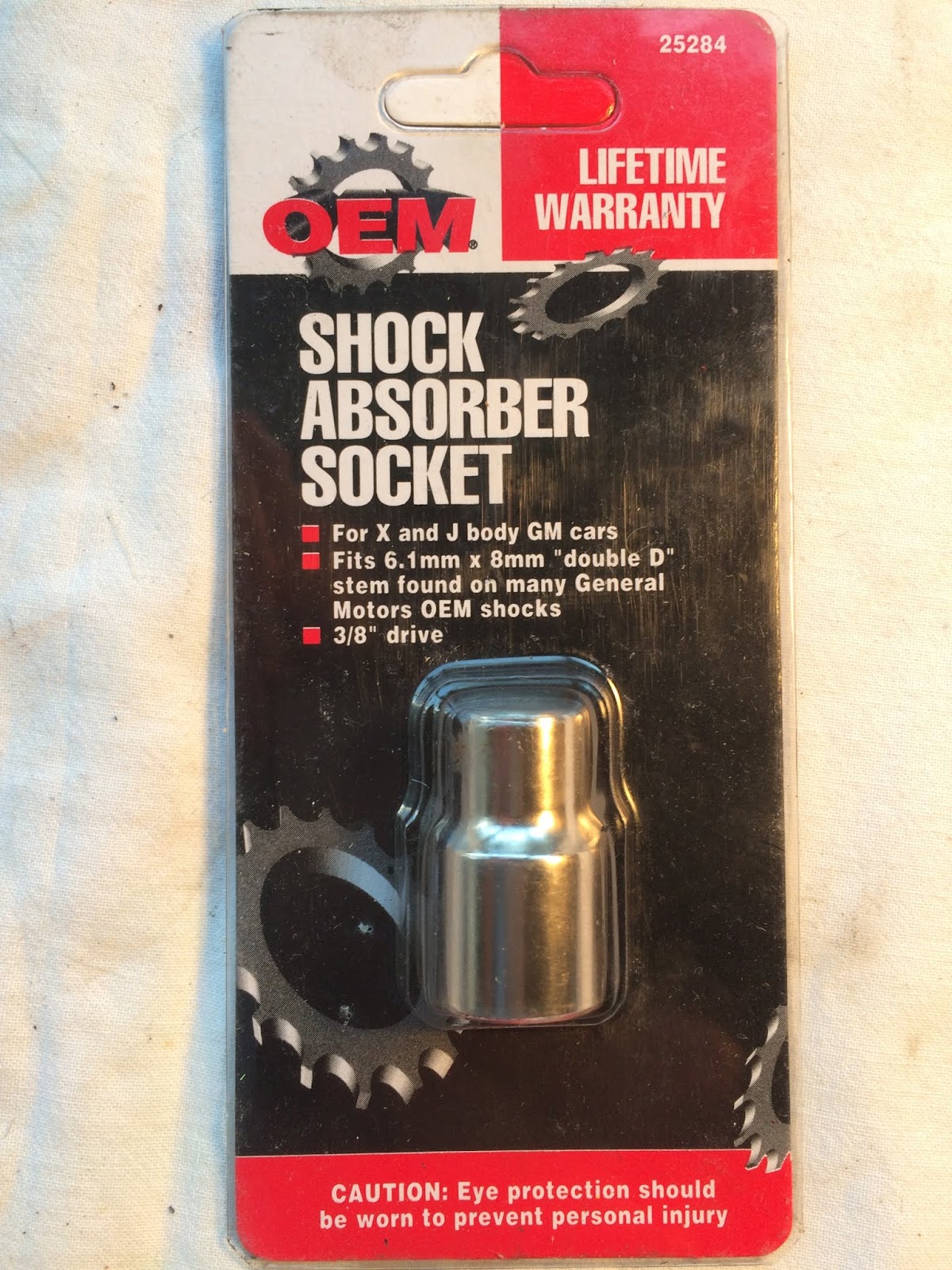
It has a slot end rather than a hex end.
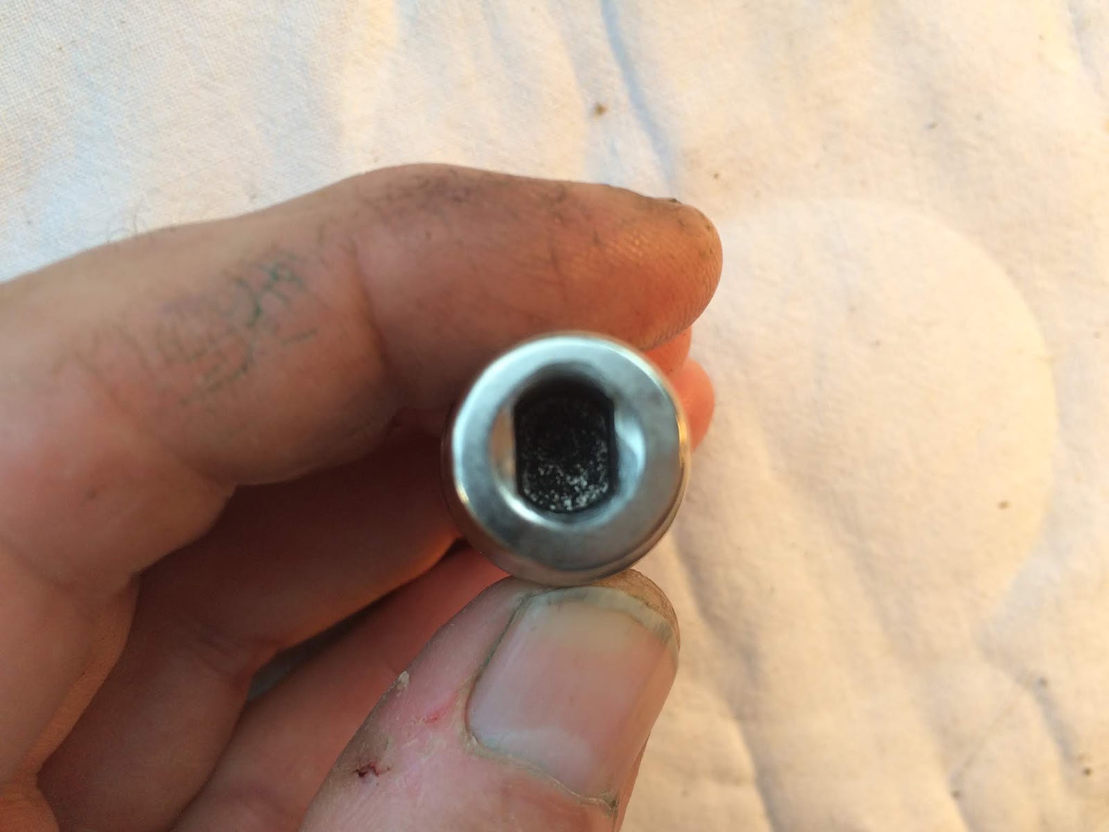
Googling ‘shock absorber socket’ and/ or ‘25284’ might be enough to find one – even if it’s branded differently. It fits quite well, but if you lightly tap it onto the special screw it grips even better.
It’s a really simple circuit.The dash warning light is simply negatively earthed by the hydraulic switch. it would be easy to put a buzzer in behind the dashboard, but you’d need to put up with it being on when you first start the car and until pressure rises. Realistically though, the red idiot light is right in front of you when you’re driving so should be hard to miss. Should be…
I bought another pressure switch from Mark Hidding over in Holland. It’s still a sealed unit and I gave it a test this morning. I thought you might like to see a video of that test.
At zero pressure the dashboard warning light should be illuminated. As pressure reaches between 60 and 70 bar, the warning light should extinguish – meaning it’s safe to drive the car. If pressure drops to below 60 bar, the dash warning light should illuminate again. the test shows both of these tests.
Triggering at 60 bar, the switch is *just* within spec. I may dismantle and clean my other switch and see if that alters the trigger pressure. Ultimately I will just recalibrate it if need be.
If you can find a local outlet that sells furniture or suitcases (or both!), get some large sachets of silica gel from them. Wherever you store your tank, loosely close the apertures up – if only for dust – but dangle a couple of silica gel sachets inside on wires. They will take some moisture out of the air.
Could you blow warm dry air through it with a hairdryer, then dangle some silica gel sachets inside it and then wrap it all up in polythene sheet while the air is till dry? It might be better than nothing and would probably be enough under the circumstances.
As Peter says – wing removal is straightforward. Seeing is believing:
Several options.
Try local crash repair places – but they are probably going to prioritise lucrative insurance jobs over small work. And they won’t know Ds.
Rust. sounds like you will need metalwork doing. it might be best to let somewhere that knows Ds looks at what is needed, source the repair panels and potentially do the work. They are unlikely to quote cost until they take the job on and start removing paint and rust and see the scale of things. South East? you could try contacting PallasAuto down at Northfleet in kent. If they’re not interested in taking a small job on, they may at least be able to refer you to a company they use/ work with.
You could try Jamie at DSWorkshop but I think he uses someone else to do his paintwork.
How about Chevronics in Hitchin, north of London.
the big problem you will have is that most places are fully stacked up. Sometimes for more than a year. As peter says, your best course of action is to search around for someone, agree the broad work and get put in their diary. in the meantime leave it alone or try to delay further rust yourself.
Thanks. I know ‘reverse crunch’ is used in bvh set up but a car with a clutch pedal doesn’t have a slave cylinder and so not the same push rod. I’ve just looked at one of the ‘servicing the goddess’ videos and for a car with clutch pedal, Adie uses the degree of free play down at the adjuster as the indicator of correct setting.
I looked up that pushrod in the parts manuals. Originally a 90mm rod was efi-only, but was adopted across the DS range in July 72 (for 73 model year). that coincides with the universal adoption of the diaphragm clutch across the range (had been efi-only), so that seems to be the reason. It means that later carb cars already have the longer pushrod, and that my 90mm find could be from the gearbox of a later carb car.
Congratulations. So along with mine, that’s two more 68s back on the road.
There are a few bits in the accelerated idling device. Have you got them all? There is the slide valve:

And then the plunger on the end that seals the hole.
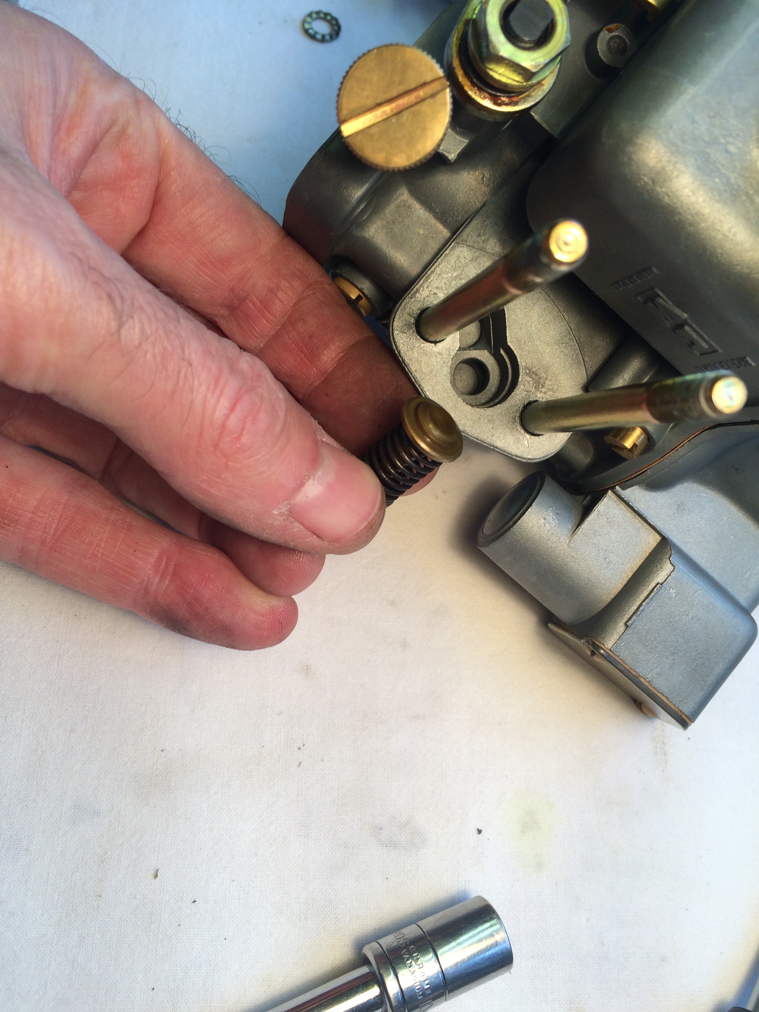
Notice also the slit brass sleeve around the plunger.

I can’t follow your logic re: timing, but i suspect that is because there isn’t any 🙂 If you’re happy, you’re happy.
Suspension. Yes, one sphere could have deflated at a different rate to the other, or even failed. As you say – try swapping the spheres over to the other sides.
It’s possible to have them tested to establish their remaining pressure. But if you can afford it, buying two new ones *should* give you a better ride. And if it doesn’t well – you’ve eliminated the spheres as the cause.
It’s worth giving the height corrector a clean out but be warned that it contains many small and easily lost/ damaged parts. Also if, in removing/ fitting it you upset/ alter the rods and levers that are connected to it, your suspension may start acting oddly. Just be careful.
Air. That extender normally stays fixed to the car and the sphere unscrews from it. My understanding is that the high pressures in the system cause the fluid to break up air pockets into many smaller bubbles. Bleeding the system allows it to carry this aerated fluid away back to the reservoir. Regardless of the mechanics, if you bleed the system after changing the spheres you should be fine.
How are you getting on with your clutch these days Ian Anderson?
I’m digging this thread up just to add to the pool of learning (or confusion?).
Having got my car on the road, I’ve tried setting up the bvh using Adie Pease’s “reverse crunch” method: as the reverse gear has no synchromesh, you put the car in reverse gear and if there is a ‘crunch’ it means the clutch is dragging. You gradually wind the adjuster nut in (tighten it) until there is no crunch when you put the car in reverse and that is the correct setting point…..
As i wrote in an earlier post here, with a new clutch pressure plate and friction plate from Citroen Classics my nut is now fully wound in and i’m still getting a slight ‘crunch’. i’ve run out of adjustment. The car drives, but i know it’s not quite right. These days Citroen Classics say their friction plates are (the correct) 8mm thick. I don’t know if they said that when i bought mine a couple of years ago. Doesn’t mean they weren’t and I assume the one i was sold was fit for purpose.
A friend in the US said that when he rebuilds engines/ clutches, he now puts a washer behind the fulcrum of the clutch fork. He says this buys a few extra mms of adjustment on the clutch. As my engine is back in the car now, this doesn’t feel like an option but i had a similar idea. The clutch push rod (between the clutch cylinder and adjuster) on a ‘standard’ Ds is 80mm long. BUT, on an efi car it’s 90mm long. If i fit a longer push rod, then the extra length will mean that I’ll have more adjuster sticking out the back of the fork and more scope to wind it in.
if i use the full 90mm rod, there is a danger that the hex of the adjuster starts to rub on the gaiter of the steering rack. I would also want to be sure that when there is no pressure in the cylinder, the longer rod doesn’t prevent the clutch fork travelling fully as it should (though the notional distance between cylinder and fork will be about the same – it’s just that it will be made up of more push rod and less adjuster).
I happen to have two bvh gearboxes from vehicles unknown under sheeting behind the shed at the end of the garden. The first rod i pulled out was of course 80mm, but the second was 90mm 🙂
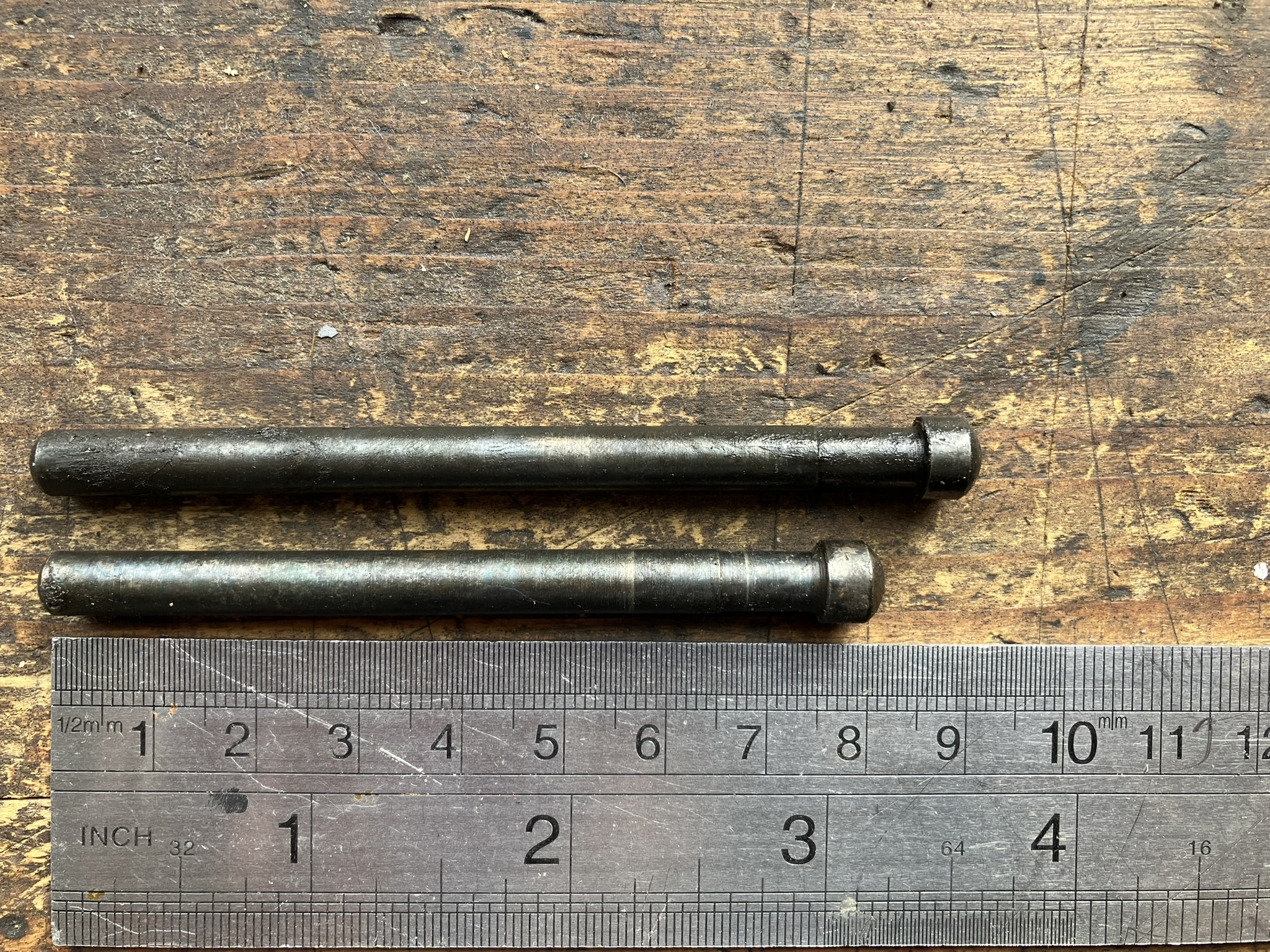
I’m minded to try the full 90mm rod to start with, and if that creates complications with the rack, then maybe cut it down by a few mms and then by a further few mms if problems remain. If i ended up with an 83mm rod, it would be no worse than the washer trick. It’s tight behind the radiator, but I *think* it’s relatively simple to pull out a rod and slip another in.
Ultimately of course, this will be a work-around and doesn’t explain why my new clutch has no more adjustment. As the clutch wears, i’d expect to have to turn the nut out, but that shouldn’t be for quite a while. I’m not the only one to experience this issue (see other messages in this thread from Ian) and there could be several reasons for it, including badly (re) machined parts, too thick plate.
I know you are (still?) restoring your car Colin. It was your blog that inspired me to do my own: imitation and sincerest form of flattery and all that.
Of that ownership, how long was it/ has it been off the road?
-
AuthorPosts